ALC/OnQ Hardware Question

Acecannon. Did you land all the auxes on the 66 block as well and did you then connect them on the 'wiring room' or 'field' side of the 66 block?

My thoughts are that I have a few 4 and 5 ways and the distro modules provide nice convenient ways to conenct up to 3 auxes to a dimmer whereas i think this may get messy with a 66 block.

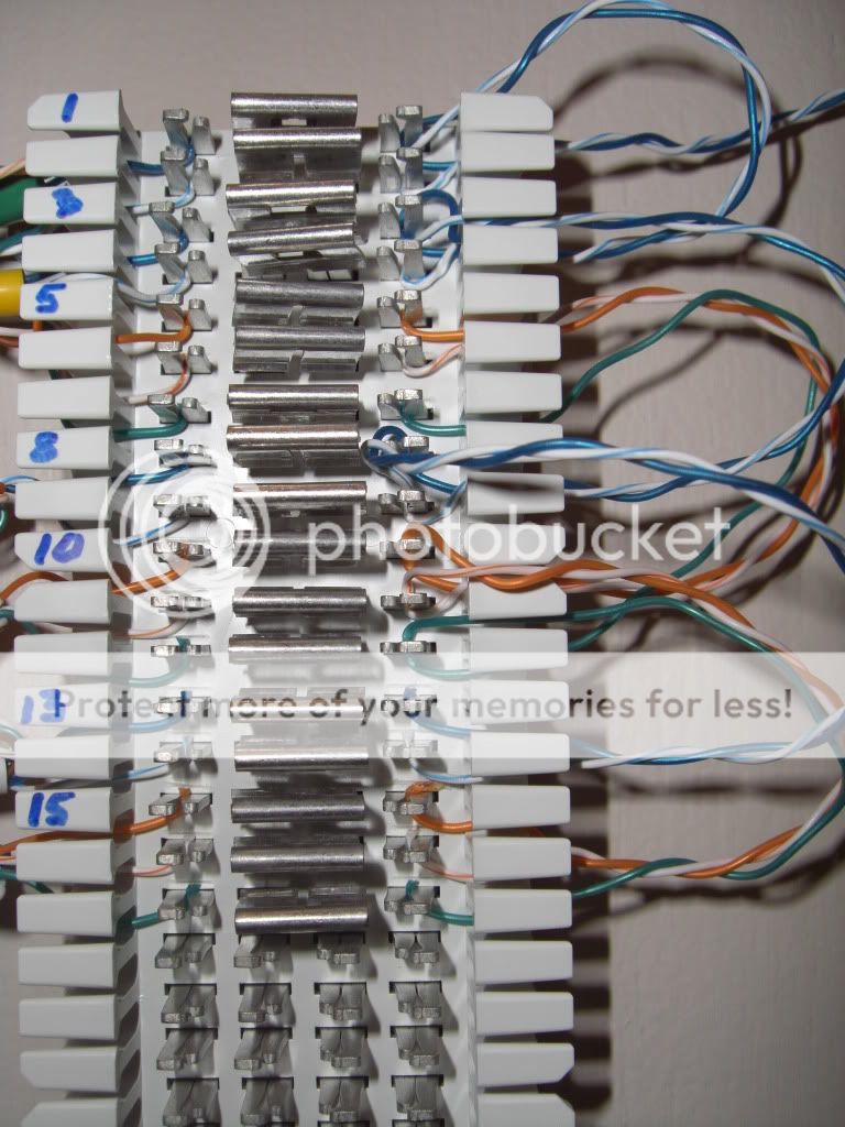
The switches and their aux connections (if needed) land on the left (field) side. I made connections to the ALC bus AND the aux's on the right. For multiple aux's, I just used 3 conductors twisted together, ran them through each set of punchdown's for each switch using the "non-cutting" end of the punchdown tool. This way, each aux can be removed from the equation at any time for trouble shooting. Just remove bridging clips.

CIMG2199.jpg
 
I think i understand..but can you give a closeup shot? Why are the 3 twisted together if they need to go through the forks and be punched down but not cut. Wouldnt they have to be individual?

If you know you werent going to have aux's on a switch..did you still land the aux wires from the dimmer and just didnt connect them to anything? That woudl eat up 66 block slots pretty fast.
 
Did not punch down wires for dimmers that needed no aux switches.

Blue/BlueWhite is the ALC bus. Orange/OrangeWhite/Green is aux switches.

CIMG2236.jpg
 
We bow to your experience, but have you ever experienced a delay on "homerun aux 3-way switches"? Based on my understanding these contact closure signals travel at essentially the speed of light (barring capacitance effects). There shouldn't be any delay no matter how long the wires are!

I realize I am not Tony, but I do have 3 aux switches installed, all wires are homerun to the central wiring closet where they connect to the load bearing switches' low-voltage conductors.

All work immediately, no delay. I feel certain that they indeed are "contact closure" and as such there are really no "signals" except ON/OFF. (yes/no, 1/0, whatever).

I am late again to respond.... Sorry!

No noticeable delay is seen and the aux switches are contact closure. With them being contact closure with a momentary on (top press) a momentary off (bottom press) and a center off. With this configuration you can in fact use the switches as inputs on the Elk or the HAI panels (and many others). When used this way there is a little delay as the program must cycle through to read the contact change.

Also note that there is a "Quad aux" which has 4 total aux switches on one plate and is available in 6 colors. I have used the quad aux as a simple and costs effective mode or scene switch and wired it directly to zone inputs on controllers.

Since I don't check in often, feel free to email or call me [email protected] 864-663-0011

TS
 
Thanks to TS for chiming in with the expert advise.

Acecannon. Did you land all the auxes on the 66 block as well and did you then connect them on the 'wiring room' or 'field' side of the 66 block?

My thoughts are that I have a few 4 and 5 ways and the distro modules provide nice convenient ways to conenct up to 3 auxes to a dimmer whereas i think this may get messy with a 66 block.

Tony, you said the ports on the powered hub are opto isolated. You mean ports 1 though 9 are all isolated from each other OR did you mean the that ports 1 through 9 are isolated from the ALC interface side? If they are isolated how could i have measured 0 resistance say from port 2 to port 6 on the polling loop connections. The AUX's are obviously isolated except for the special ones (port 8 i think).


-------------> I did not look at the schematic (yet) but I looked at the chipset on the board. So, I will offer a decent guess....... Since opto isolators are so cheap I expect them to be on any point where there is field wiring (any I/O point). At the very minimum the optos are on the feed back to the control board.

---------------> And..... reading chips with ohm meters can fool you. For example. On the x1 Ohm scale your ohm meter applies a higher voltage to the leads. In some meters it can be as much as 9VDC. The higher scales on your meter are low battery voltages. As such, when you increase the voltage you may jump across some chips and the short you read is not really there at all. Try a higher scale and work down to X1.


The surge supressor modules you linked to are interesting, but thats another $40 per branch..ouch..and the question is if they will really save the install? I already have a whole house surge suppressor. It seems that if you take a good hit NOTHING will truly protect you.

-------------------> True strikes are rare. Instead we see static discharge that has enough current to harm electronics. And good surge protection can always help that. also note that with added low voltage wiring you increase the number of paths for a discharge to enter your electronics while looking for a ground.


Against..thanks for looking into this thread...while the ALC documentation linked is quite usefull it's 'interpretation' seems still tricky. The good thing is that amongst the group of us I think we're starting to get a rather good understanding of the system capabilities.

All we need now are them outlet and inline modules..... B)

When the winter comes I plan to resume my ALC install to replace the 4 or 5 switches left on the ground floor and start on the upstairs. While for a few locations an ALC switch is hard to justify OCD laws prevent me from having a 95% automated lighting solution in my house. lol


Hope this helps.

God Bless
 
So, since I'm now finally making real wiring for this thing....how do I connect all these auxs together?

I have the wiring distribution module, but it seems that it's only meant for a single aux being wired in. In at least one case I have 3 aux. I guess I can wirenut them together. I don't have a 110 block like ace showed in the pics. Can more than 1 wire be punched down in the 110 block of the distribution module? I mean, 1 wire on top of another?

Those are 66-blocks, actually.

I don't know how concerned you should be, but some say punch-down blocks are not good for indefinite repeat punching-down. My feeling would be to try to punch down multiple conductors in each slot, but I dunno what that may do to future attempts if you end up needing to remove the wires.

Wire nuts or telephone beanie connectors are another option. . .

Or a 66-block. :(
 
Tri-State Elctronic part # s66m1-50, in case you needed a source with good prices.

tselectronic.com

(I have no affiliation)
 
Wire nuts or telephone beanie connectors are another option. . .

Or a 66-block. :(

Doh! I keep forgetting I have those telephone beanies....bought them so long ago, and never used them. Duh. Ya, I think that'd be perfect, just about.

turns out there's really only 1 setup in my house that has more than just a 3-way....so the ALC Distribution block seems to pretty much fit the bill. Stayed up until 4a last night wiring in the lights, but they work and I'm pleased with it.
 
Back
Top