ALC startup questions

rbroders

Active Member
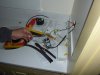
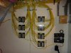
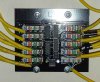
Hi Guys, after many many months, I am just about ready to turn on my ALC system. I have 158 switches (99 loads and 59 AUXes) on 4 branches wired through 12 branch hubs. Each switch has its own CAT5 wired into the box and covered with insulating heat shrink tubing to satisfy the local inspector (see pic).

I have finished all of the punch downs, and I'm anxious to start testing but I have not powered the HLC yet. The electrician has about half of the switches installed, and one of them is actually connected to a light that works! This particular light has one AUX which also controls it. So far, the LOAD switch works great, but the AUX switch does not work well. The AUX will turn the light on, but not off. Also, it doesn't seem to be as responsive as the LOAD switch. My expectation was that the behavior of the AUX switch is indistinguishable from the behavior of the LOAD switch. Can you confirm this is correct? As a test I grabbed an AUX which has not been installed, and use my meter to test the wiring. I found that ON worked great (and had a nice tactile click), but OFF did not work well. If I pushed hard enough the circuit would close, but there was no tactile click. Do you think my AUX switches are defective?

Also, I am trying to develop a turn-on/test strategy. My system has no scene switches, and will ultimately controlled by my CQC and its touchscreens. My CQC system is not installed yet, and I'm not sure its the best platform for debugging my ALC communication network. Do you know of any other software I can use? Perhaps I can just use HyperTerminal and send some kind of interrogate command. Then I could wire each hub individually to verify LOAD switch communications...

Thanks -- Bob
 

Attachments

  • ALCSwitch.jpg
    ALCSwitch.jpg
    94.3 KB · Views: 94
99 loads...holy crap...thats a pretty serious install.

They have the branchtech software which is probably good for your case. Not sure how much it is or if you want to spend that money...if i recall i wasn't that expensive.

On the funny acting switches, I think there is a few things you can test. I am going from memory here...but if you cross the red LV with the black or cross the green LV with the black this should turn the load switch on and off. The AUX is nothign more that a 2 way momentary contact switch so it essentially does the same thing but remotely.

If you can confirm that the load switch works then put a meter (set for OHMS) on the aux switch (while it is completely disconnected from the load) and put the meter on the black and red, then operate the switch. I can't remember if a shorted red is on or off, but you'll find out quick enough. Anyway..measure the resistance. I should 'infinity/overload' and zero or extremely close to zero when you operate the switch. If they both check out then there is a wiring issue.

I just checked mine and the aux switches definitely have a light tactile click to them.

I have 12 or so load switches and installed and 4 or 5 auxes and another 10 or loads and some auxes to go to complete my install. The CQC driver work great. Just FYI beelzerob reported issues using a serial server (e.g. a quadtech unit) but i haven't experienced this issue (so far i've had it on the serial server for about a month or so).

Good luck on your install. I would definitely take a methodical approach to this or things will get out of control fast with that many loads.
 
Thanks MavRic, just for the record, can you confirm that AUX switches behave identically to the LOADs they control? You say lighter tactile feel, but other than that, you can't tell if you are pressing an AUX or a LOAD switch?

I did use my meter (in continuity/beep mode) to confirm a good connection with GREEN/BLACK when ON is pressed, and an OK connection with RED/BLACK when OFF is pressed very hard from one AUX switch.

I'm ordering BRANCHTECH software now. I think it will be a big help...

--Bob

P.S. Here is a pic of 7 of my 12 branch hubs.
 

Attachments

  • LVHubs.jpg
    LVHubs.jpg
    96 KB · Views: 98
To quote MavRic - "holy crap" - I'm not sure if I'm jealous you have your entire house wired or scared.

You've started in the right place - a plan.

BranchTech - while you have ordered it, the standalone version is for the BranchTech "bridge" that is serial to banana clips for the comm bus. The SceneTech software now has the equivalent of BT embedded in it and works with multiple branches through the interfaces. I highly recommend the standalone version for what you are embarking on _and_ future troubleshooting.

As an observation, your picture doesn't have the expansion module for branches 2-4 and I would recommend an 8-port RJ45/110 module so all your branches and serial connection are simply patch cables and you aren't having to crimp cables. Makes testing/troubleshooting much easier.

I haven't done an ALC install this large myself, but have done a number of other very large installs of both Network and Telecom that needed well defined approaches. Keep the aux-switch testing separate from comm testing, aux switches are purely physical wiring and can be tested/fixed individually whereas the comm builds to a system-level test. My steps for comm testing:

Prerequisites:

- Solid documentation for each hub with switches and addresses;

- Disconnect each hub so it is stand-alone for the first part. If any switch on a branch is wired backwards or wrong it will "clamp" the entire branch. Unfortunately, the hubs you have don't have the disable switches on them.

Hub-level testing:

- STOP and meter your comms first - A to B, A to Ground and B to Ground - AC and DC - you should see "zero" across the board. I didn't do this after a lightning strike and smoked my BT bridge with ~40VAC on the comm lines. I got lucky. If you can disconnect the hubs BEFORE power is applied I would recommend it so if there is a problem it is limited to taking out a hub and not an entire branch.

- Using a laptop, BranchTech and the BranchTech bridge test each hub independently and verify the addresses you are expecting and device types are there.

- Don't worry about validating the loads yet - this is to fix any wiring issues that are found (for comms) and update documentation as necessary.

- Make sure the automatic polling runs clean for a number of passes. This is not anywhere near as fast as the lighting controller will poll so there may be issues later but this is a good first test.

Branch-level testing:

- Connect the hubs that should be on a branch. If all your verification is good from the hub-level testing there won't be any duplicate addresses

- Test the entire branch with BranchTech to make sure everything is clean and shows up from the first hub in the branch (at the hub).

- Connect the leads back to the lighting controller and test each branch again from there before connecting to the controller.

System-level testing:

- Connect the branches to the lighting controller and expansion, one at a time, and test with SceneTech and your serial port connected directly to the lighting controller. The standalone BT doesn't know how to talk to this controller, only the raw protocol, so you need to use the BT that is embedded in SceneTech.

- Next comes validating that each branch/device is the one you expect it to be. You can obviously skip this but it can make the CQC side a lot of fun if there is a mismatch!

- With one laptop running the ST software and connected to the lighting controller, get out your other laptop and vnc/remote desktop into the first (wireless) so you are portable to walk around the house.

- Device by device make sure that you can toggle it via the lighting controller and the right switch is activated. 99 loads will take a while!

My 2 cents. Best of luck, keep us informed!

Jay
 
Thanks JayH, what a great response!

My BranchTech order fell through, but thanks to your explanation, I think I'm better off with scenetech anyway. I'll use my existing serial interface to test each hub and save me the cost of the dedicated "serial to banana clips" device.

My LEM was not installed when the photo was taken, but it is there now. I like the idea of patch cables and a punchdown. I only have four RJ45 heads to crimp though, so I think I can manage it.

I'm definitely trying to test the AUX switches first, and so far not one works properly. I'm quite concerned. My understanding is that the AUX switches should behave identically to their LOADs and the HUBs do not need power for them to operate. I OHMed an AUX and it didn't work well, so maybe I have a part problem.

I have very good documentation, and all of my wires are carefully labeled. I didn't go with the enhanced branch hubs because they are lots more expensive, and it seemed that the switches on the back would be impossible to access anyway. Hopefully I won't regret that decision too much...

Meter the COMMs? Really? This seems like a bad idea. Doing a resistance check puts a voltage across the circuit which could damage it. I'm not sure what were looking for anyway, a short in the line? Hmmm.

Thanks again -- Bob
 
YES, your aux's should feel and behave identical to the load switches. in fact, if I hadn't written them down, I really wouldn't be able to tell which switch is switch once the wallplate goes on.

I will say that some of my switches (whether load OR aux) have different tactile feel to them. Some feel softer, and some feel like they're actually sticking when I press them...though they don't stick (or the bulb would start dimming).
 
I think the hub with the dip switches are intended to be mounted with the switches facing you in a 2 gang box. They are low profile enough that you can fit a decora maxi plate cover them and cover the whole thing up. My hubs don't have the swtiches but i plan to mount them in that way.

There is no way ALL your AUX's are bad...there must be a wiring issue of some sort.. can you take a real close up shot of one the hub where you do a 3way so we can take a look?

Did you follow a fixed convention for the ALC LV colors vs Cat5e colors vs Hub punchdown colors?
 
I don't think you can wire up a hub and then turn it over to access the switches easily. When you have 15 cat5s punched into it, it becomes rather unwieldy. There is also the chance that just turning it over and putting into the box could cause one of the wires to "un punch" itself.

I don't think all of my AUXes are bad. There are only a few (2) loads in the house that are wired, have lights installed and have power turned on. Of these loads, neither AUX is working (one turns the light on, but not off, and the other doesn't seem to do anything). I'm not panicking yet, but I am getting nervous.

Here is the wiring convention I followed:

Code:
Signal   Switch Wire	   CAT5 Wire
TX+	  YELLOW			BLUE/WHITE
TX-	  WHITE			 BLUE
12VDC	NA (Hub Power)	White/Brown
GND	  NA (Hub Ground)   White/Green
AUX ON   GREEN			 ORANGE
AUX OFF  RED			   GREEN
AUX COMM BLACK			 BROWN

I am fairly confident of the hub wiring (brown wire to brown mark, etc.). I did reverse the comms on a few hubs and had to go back and fix them all BLUE/WHITE on the left and BLUE on the right. I send a zommed hub picture tomorrow...

Thanks -- Bob
 
Close-up picture of one of my HUBs...

--Bob

P.S. Just realized I need another power supply for my LEM's branches.
 

Attachments

  • L3HubCloseUp.jpg
    L3HubCloseUp.jpg
    95.8 KB · Views: 58
Close-up picture of one of my HUBs...

--Bob

P.S. Just realized I need another power supply for my LEM's branches.

Two quick observations:

1) 2 wires in a single 110 punch usually doesn't work well. I see you have them stripped & twisted but you still have the risk of them being broken;

2) Positions 8 & 9 have the aux switch leads bridged (parallel across both) for where you need to connect more than 1 aux switch (ie, twisted wires). I have no idea how the switches will behave since it appears you have 2 physical switches wired together along with their aux switches.

Jay
 
Yeah, I'm not thrilled about the two wires in a single punch on connection 6. I taped the CAT5s together so there will be less stress on the wires, but I'll definitely keep a close eye on those.

I know the AUX connections are bridged from 9 up to 8. Really, the data connections are independent, so you could just as easily say they are bridged from 8 down to 9, but that is how it is drawn, so that is how I wired it. In this case the LOAD on connection 9 has three AUXes. The LOAD on connection 8 doesn't have any AUXes. For future purposes, I wrapped the three AUX wires back around LOAD 8's yellow sheath and taped them. There are three yellow CAT5s connecting to 8, but you can only see two in the picture.

My electrician and I went through the lighting today and almost all of the switches and auxes work perfectly. Phew! The first two switches we tested seem to be broken though and we're going to replace them. I'm still waiting for the test software so I can see if the data bus is working...

Thanks -- Bob
 
Yeah...other than the previously mentioned multiple cat5's in a 110 punch the wiring looks good. Seems you're following the same coloring scheme is used. Still so stupid ALC uses Orange for ON and Green for OFF on the hubs..doesnt really make sense to me.

The TX+ and TX- are all paralleled anyway as far as i know anyway.

You said that you got wacky ohm readings when you tested the aux switch completely unwired right? If that is the case it would seem the auxes are indeed bad.
 
The AUX eventually gave good readings, but the switch needed to be pressed very hard. My electrician figured out how to remove the toggle plate and re-align the springs, and that seemed to help quite a bit.

One thing we noticed is that the dimmer switches have an extra off position. If you press really hard on the bottom of the switch, the button depresses slightly, and sticks there. I believe that this creates an "air gap" which completely kills the circuit and makes the light fixtures safe for bulb replacement...

Speaking of off behavior, I have a couple of LED ropelights which are connected to ALC Dimmers (by mistake, the ropelights are not very bright), and I noticed that the ropelights are on about 30% even when the ALC dimmer switches are OFF! Has anyone else noticed this behavior?

--Bob
 
Speaking of off behavior, I have a couple of LED ropelights which are connected to ALC Dimmers (by mistake, the ropelights are not very bright), and I noticed that the ropelights are on about 30% even when the ALC dimmer switches are OFF! Has anyone else noticed this behavior?

If the dimmers do not have a neutral wire, then what you are probably seeing is the current bleed for the power needed to operate the dimmer. Not sure if ALC makes a dimmer with a neutral wire, but if they do, it is what you need. Or replace the dimmer with a switch.

Speaking of ALC, what ever happened to Number 20?
 
Number20 / TS has gone pretty quiet...no idea what the status is on them getting the molds and starting production in the USA. It's certainly not moving at the speed i was hoping for..thats for sure.
 
Back
Top