Touch sensor: strip of metal, throw relay?

One way to do it is to monitor the current draw of the actuator. It will rise if it hits resistance. . . I think that is how car and garage doors work.

Do you know if there is a ready made solution that I can purchase or will I have to build it or pay someone to?

Thanks.
 
Do you know if there is a ready made solution that I can purchase or will I have to build it or pay someone to?

I have been promising a new series of smart I/O boards for a while now so I hestitate to make any more promises
but I do have a bunch of new boards ready to go, I am just working on the documentation and web site right now.
One of the boards (in this series of new boards) in the planning stage is an H-bridge motor controller so your application has actuallygiven me a few
ideas for features that could be built in (such as a motor current reversing option)
 
Option 1

I dont beleive this is the "right" soloution for all applications but what about a circuit interruption/resettable fuse in the power lead to the actuator at a level closeto but above the nomoinal current. this way it would not hurt anyone. but the downsides are
1. it wont automatically reverse (hope someone is not pinned),
2. you would need to reset your protection device when someone screws up.

Option 2

What are you planning to use for the normal open/close stops? Maybe a garage door safety circuit with a "pneumatic switch" edge. if these get crushed it tripps the sensor. you would then need to decide what to do when it gets tripped, maybe wire this to a relay in the power circuit to cut power when it is tripped?
 
I have been promising a new series of smart I/O boards for a while now so I hestitate to make any more promises
but I do have a bunch of new boards ready to go, I am just working on the documentation and web site right now.
One of the boards (in this series of new boards) in the planning stage is an H-bridge motor controller so your application has actuallygiven me a few
ideas for features that could be built in (such as a motor current reversing option)

I'm looking forward to seeing what you have to offer. I'm always looking for new ways to make my apartment cooler, so I'm always in the market for useful electronic components.
A while ago, in a different but related thread, someone suggested using a power spike detector, but I was unable to find one anywhere. It would be a nice feature to have something like that built onto your new board that would reverse the current if there is too much strain placed on the motor. Maybe this could be detected by a power spike?

Option 1

I dont beleive this is the "right" soloution for all applications but what about a circuit interruption/resettable fuse in the power lead to the actuator at a level closeto but above the nomoinal current. this way it would not hurt anyone. but the downsides are
1. it wont automatically reverse (hope someone is not pinned),
2. you would need to reset your protection device when someone screws up.

Option 2

What are you planning to use for the normal open/close stops? Maybe a garage door safety circuit with a "pneumatic switch" edge. if these get crushed it tripps the sensor. you would then need to decide what to do when it gets tripped, maybe wire this to a relay in the power circuit to cut power when it is tripped?

1) That might work, but I need something "idiot-proof", because if my roommate activates the safety feature and then can't figure out how to reset it, he would probably leave my door wide open and take off, then justify his actions by saying that it's not his problem and he shouldn't have to deal with that. I guess he's half right, though. I don't want anyone in a situation where they cannot open or close the door because the actuator has no power and is locked in position.
Ideally, the safety mechanism will be the same as if I hit the "open door button" -- just as if it's a toggle switch, but it is activated by excessive force (or any force) being applied to the door.

2) The open close stops will be the limit switches that are built into the actuator that I plan on buying. I'll look at the "pneumatic switch" idea for the safety.

Thanks guys.
 
there are fuses that will reset themselves when the current is reduce after it is tripped but the problem with the actuator is that it is possible that it will have your finger pinched like a vice grip in the door and yes, the power has been disconnected but the screw mechanism will still hold you there, screaming like a little girl :blink:
Most actuators are capable of a tremendous amount of force, so, for that reason a reversing circuit would be a must in my opinion. Now, the problem becomes one of setting the proper threshold. If your circuit is capable of monitoring the current flow to the motor and you have an adjustable threshold for it to trip at then the trick will be to have enough power to close the door but be sensitive enough to reverse when needed. Depending on where you live, winter might pose a problem as it will take more power when the door is cold and stiff or if there is some snow build up. The other issue is that you have to set the actual closed position accurately enough to stop right at the moment, closed, but not over current tripped. Around here, with weather stripping on doors, a person will usually close a door and then give an extra push to compress the stripping before the bolt fully engages.
Anyway, what I am getting at is that this might be a little trickier than it first appears but it will depend a lot on the door construction and your location.
 
there are fuses that will reset themselves when the current is reduce after it is tripped but the problem with the actuator is that it is possible that it will have your finger pinched like a vice grip in the door and yes, the power has been disconnected but the screw mechanism will still hold you there, screaming like a little girl :)
Most actuators are capable of a tremendous amount of force, so, for that reason a reversing circuit would be a must in my opinion. Now, the problem becomes one of setting the proper threshold. If your circuit is capable of monitoring the current flow to the motor and you have an adjustable threshold for it to trip at then the trick will be to have enough power to close the door but be sensitive enough to reverse when needed. Depending on where you live, winter might pose a problem as it will take more power when the door is cold and stiff or if there is some snow build up. The other issue is that you have to set the actual closed position accurately enough to stop right at the moment, closed, but not over current tripped. Around here, with weather stripping on doors, a person will usually close a door and then give an extra push to compress the stripping before the bolt fully engages.
Anyway, what I am getting at is that this might be a little trickier than it first appears but it will depend a lot on the door construction and your location.


I see your point about the weather stripping. I live in Montreal, Quebec, Canada, so we need to use it also. We have some pretty bad winters here. What if you had a knob (like a volume knob) to set the sensitivity? That way you could adjust it in the winter to be less sensitive and accomodate the conditions that you mentioned if need be.
 
ahhh, fellow Canuck eh?
You could have a sensitivity adjustment or automate it with either a temperature sensor, or better yet, measuring the average current needed and adjusting the threshold as the average changes over time. It all depends on how complex you want to make it!
 
ahhh, fellow Canuck eh?
You could have a sensitivity adjustment or automate it with either a temperature sensor, or better yet, measuring the average current needed and adjusting the threshold as the average changes over time. It all depends on how complex you want to make it!

Awesome! Those ideas are brilliant. The problem I have is that I need to keep it fairly simple and not relying on a computer -- in particular a computer running windows. Wasting days of my life because of hardware incompatibilities and virii are one thing, but if I became an amputee because of microsoft, I would have a whole new hatred for them.

I really like the idea of measuring the average current needed and adjusting the threshold. That could be a reliable and versatile way of dealing with that problem. The threshold could be quite higher than the spike that happens when the weather stripping is being pushed in at the last moment, because if someone does get caught in the door, I'm pretty sure that they would give it a really good shove. Maybe a combination of a knob and the "smart" average current reading adjustment would be good just in case people would want to manually troubleshoot certain situations.

So when are you building them and how much will they cost? :)
 
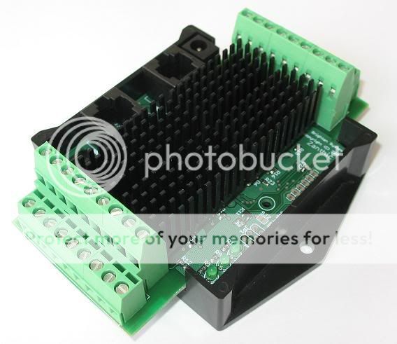
I am going to follow the same format for my other boards , like this

hiside.jpg


but will have 4 H-Bridge drivers, each capable of 5 amps with current feedback and analog inputs for position sensing and a few extra digital inputs for limit switches or user control. Configuration will include the ability to set the current threshold and choose between stopping or reversing. Others have shown some interest in doing other motor control for blinds and for robotic use so if the configuration has enough features it should be useful in a number of ways.

Looks and sounds great! I guess I'll have to come up with a use for the other three H-bridges. Will the board be powered by 12VDC so that I can use my deep-cycle battery to power it? How will the configuration be done?
This sounds very promising. Can you give us an idea of how much you will charge for these?
Thanks.

Add three more doors! :D
Yes they are 12VDC. I am working hard at getting this whole system up on my web page and am hoping to have the initial info up over the next couple of days but here is the over all concept...

Each of the boards comes with a 500Kbps network built in, based on CAN (Controller Area Network) and you buy the hardware and then you can download the firmware that you want that configures the board to best fit your application. For example, a board might have 32 I/O pins and somebody might want 32 digital inputs and the next person wants 8 analog inputs, 16 digital inputs and 8 dimmer outputs. In the case of the H-Bridge board, you might want 4 H-bridge devices and use the 8 analog inputs for reading temperatures and not use any feedback to the H-bridge devices.

Configuration is done through the CAN bus with configuration software that runs on your PC. It does require an interface from USB to CAN which does add to the initial investment because the overall concept is to have a number of boards all networked together and the configuration software can connect to any board, or any device on a board and at any time download new firmware to change a boards "personality". Once a board (or boards) are configured, they can run stand alone and send commands across the network automatically. This means in your case, you could have a board in one room that has an infrared remote control that sends open/close commands to your door in another room. It also means you could add a board that includes an RS232 interface and control it through a home automation package (a driver for CQC exists and I am hoping to have others added)

As far as cost goes, I don't want to commit without having designed the board but it should be under $200 and possibly less than that.

Well, I may not need to use it for three doors, but I should be able to find something cool to do with them.
This CAN stuff is very interesting. I can't believe it's the first time I've heard of it. Seems very useful and versatile. The problem is, I don't have an extra $450 kicking around the house to spend on an interface, especially if I'm going to have to spend around $200 on the board. I hope I'm wrong about the cost of the interface, but that seems to be the price at which they start. :D
Although I would love to interface directly with my automation system, I think that I would have to ask you to configure the board for me before shipping it if that would be possible and I would use it as a stand-alone device only.
 

The CAN-4-USB/FX interface that I sell (www.zanthic.com is my primary business, Brightan is my hobby business!) is normally $249 so that is better than the $450 that you found but I realize that some will find it odd that you would need a $249 interface to configure a $200 board but the entire idea is to have an entire network of useful controllers and the interface is necessary to get all the features. I have played around with equipping some of the boards with an RS232 port that could be used for configuration but it really doesn't work that well for a number of reasons, slow being just one of them.

As far as configuring the board before shipping, I am open to something like that but I suspect in the end you'll want to be tweaking the settings to suit, and, you'll find out how many other cool things you can do with it (both the board and the interface...like plugging the interface into your car's OBD-II diagnostic port) and if not, I'm sure we can work something out.
 
Back
Top