EOL supervised zone switch puzzle

Quixote_1

Active Member
Hi,

I have a tricky puzzle that I'm having a bit of a tough time figuring out and thought I would present it to you guys to see if there is someone here that is really good with logic. I've spent about an hour on this so far (mind you, it was very late, so my brain may have been scrambled).

I have a switch that has 3 positions and three terminals. In the middle position, the switch is open. The other two positions switch the middle (common) pin to connect with either of the two other pins. I am trying to create an override switch for an output that would be neutral in the middle position, ON in the top position and OFF in the bottom position or vice-versa. I am obviously using rules to accomplish this.
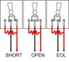
If I can figure out how to set it up so that it's shorted in the top position, closed in the bottom position and open in the middle, I should be able to get the output to behave the way I need it to. So far I have not been successful in arranging the switch positions the way I'd like them to be. The middle needs to be neutral because otherwise I will turn the output on or off as I adjust the switch to the neutral position.

Thanks for your help! Diagrams would be very helpful!
 
I believe I'm missing something. How does a three position switch and an output apply to an EOL supervised zone?
 
So you are going to connect a three-position switch to an input zone, so that you have manual control over something else?

The first thing you need to do is differentiate between the two switch closures, and your post subject has the answer -- use an EOL resistor for one of the positions and a dead short for the other. This gives your switch three distinct states -- open (in the middle), shorted-closed (in up position), and EOL (in down position).

Define the zone as EOL supervised and then work the rules so that you key off the state changes (e.g., BECOMES NOT SECURE - SHORTED and BECOMES NOT SECURE - OPEN and SECURE). (Don't have RP2 handy at the moment so this might not be exactly right.). Once you find and test these transitions, add the logic for your application.

Yes, you'd think that would work, but it doesn't. :angry2:
The wiring seems to be more complicated than that for some reason. It seems that the resistor still need to be in the equation for the SHORT to work. I tried just touching the two wires together and setting the output to turn on when it's SHORTED and nothing happened.
As I said, I played with this for close to an hour before I got too frustrated and went to bed.
I'll put together a diagram later of what seemed to work, but I can't figure out how to work the three position switch into the circuit.

Thanks
 
Ok, apparently I'm having trouble with the terminology.

I thought that a short would occur if I closed the two zone wires together with no EOL in the circuit. Nothing happens. I also thought that if I just leave the entire zone circuit open I would have an "open loop". Still nothing. Closing the circuit with the resistor in series does get results, but neither of the extended EOL zone states seem to be working for me.

What am I missing?

I've attached a diagram of the switch.

switch.jpg
 
Here is the wiring. Be sure you are using zone definition Type 3 or 4.
 

Attachments

  • wiring.jpg
    wiring.jpg
    24.3 KB · Views: 3
Thanks. I'll try that out.
I don't really want to use a burglar zone. I was hoping to use zone type 16 (non-alarm). Is that not possible?
The switches are for LED lights and I don't want to have to bypass them all the time when leaving.
 
Well, minor progress.
The wiring diagram that you showed me worked when I switched the zone to definition 4: "Interior Burglar", and set it to type 3: "EOL Supervised on Short".
I had actually tried that wiring arrangement initially, but I was using definition 16: "Non-alarm", which did not give me the 3rd and 4th type options for supervised on short and supervised on open.

The problem now is that whenever I put the switch in the short position, the keypad goes nuts and I need to hit the star key to shut it up.

What is the reasoning behind not allowing us to use the other two types of zone supervision with a non-alarm zone? Is there any way around this? Also, I don't want to always have to bypass the zones when I want to arm the system.

Thanks!
 
I believe for non-alarm, your only real option is to do a rule that fires every minute or so and evaluates some options... if you can hook it to one of the first 16 zones, you can do a rule that:
Every 1 minute
If Zone XX voltage is X Then...

You'll get full voltage on short, some lesser amount on the EOL resistor, and 0 on open.
 
I ended up putting them in an area with no keypad, and turning off the vocal announcements that were triggered when the zone caused an alarm. It works well now.

Thanks to both of you for your help and suggestions.
 
Back
Top