Ok, bare with me...I'm trying to do this from memory, and based on the pictures, and the thread, this was 7/72007 that I am trying to remember from! Also, <insert legal stuff here>. I.e. if you do damage to you your person / house / dog / fish / pink-panther-diamond / etc....I didn't TELL you to do this...it was just for information. Remember, this WILL void warrenties, also this mod is NOT UL approved (especially since this will mix high and low voltage VERY close together!!).
First thing is first, open up the box. This, as indicated in other parts of this thread, is not too hard. I also started at the "bottom" plug end and just stuck a flat head screw driver into the device. Just be careful, as you need to pry back the sides all around to break the glue bond, PRIOR to working it free. Then it is a matter of "popping" the cover off where the tabs are.
Be careful you do not damage the LED or programming button.
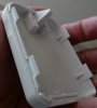
After you have opened the unit, you can see that there is a board in there. Take it out and flip it over. You will see a "thing" that looks like this <image P1010501.jpg>
This is the relay. The thing that is flipped on and off by the PIC microcontroller that is on the board next to it. Interestingly enough, they are using a RF PIC in this design! I've used this guy in RF designs...never to read from a power-line.
Anyway...
As shown in the next image, you will need to de-solder this part. <P1010498.jpg>
** I also think that there is a wire that connects from the hole that is near the "double" slots on the right hand side of the last "board" image (P1010499.jpg) to the bottom left most hole that looks like it has solder goop on it. This (I believe) is the neutral wire. That is why we need to isolate that pad (see next paragraph).
You need to isolate all the HV from the LV. I believe (from memory and looking at my images) that there is a trace that you need to cut...as shown here: <P1010502.jpg>
You will need to lift the resistor shown in this image: P1010503.jpg
Yeah, I know, I can't really remember. Looks like someone will have to go through and verify the voltage on that pin...or I will next time I need to make up a module.
Next, attach a small piece of wire to the relay, as shown here:
<P1010505.jpg>
You should make the wire large enough for the current you are going to push through the module. Remember, it is rated 300W for AC voltage. It is NOT 300W for DC. There is a de-rating...which I can't find a link to right now. Does anyone have a link??
To be "ultra" safe (HV / LV) I put a piece of electrical tape to ensure that there is no immediate contact to any of the relay's parts. The idea being, even if the tape moves, wears, etc. the Relay SHOULD be soldered in place "hovering" above the board at least the tape's thickness.
The wire will then get soldered into the hole that was created when the "neutral" wire was taken out. <p1010509.jpg>
When you are done, snap it together and MAKE SURE YOU MARK IT RELAY!!! The green wire came from an outdoor lamp that died on me. It made a perfect way to "plug" into the relay module and provide me with wires to use wire twists on. I have used this for pushing the button on my garage door opener as well as turning on a PC (I wired this in parallel to the "power" button).
<P1010510.jpg>
As a final note, before snapping everything back together, if you look at this image:
<P1010499.jpg>
Notice that there are two slots in the board, on the right hand side (in this image). If you line that up with the "top" lid and cut two slots there...make them small slits so that the plastic can help hold you plug in...but this will create the "pass-through" slots for you. I do this on modules that I am NOT, repeat NOT turning into relay modules. I prefer to keep my HV and LV mixing to a minimum!