Documentation quirks, errors and suggestions.

rossw

Active Member
In the latest PDF I have (3.2.13), I just noticed something that irked me, and there are enough of them in the doco that I thought it might be worth starting a thread for them.

Example 6.4.1, the description states that "if temperature is less than 37 degree" yet the code will turn on the output for "less than or equal to". Similarly, it says "greater or equal to 39 degree" yet the code achieves this by the non-intuitive process of testing for "greater than 38.9". I know these are small points, but there are a lot of users who look at the examples and get even more confused! Consistency and accuracy in the documentation has to be a good thing, right?!

Next, you go on to say that the code, as presented, wouldn't work - and why - and I have no argument with that, but what I do have to ask is.... (and I keep comming back to this) - WHY OH WHY do you have this total fetish with using subroutines?!

Code:
START
   TSTLE T3 370
   CALLSUB HEAT_ON
   TSTGT T3 389
   CALLSUB HEAT_OFF
END
HEAT_ON:
   SET OP1 1
   RET
HEAT_OFF:
   SET OP1 0
   RET

is FAR less readable than

Code:
START
  TSTLE T3 370
  SET OP1 1
  TSTGT T3 389
  SET OP1 0
END

And in order to make the code ACTUALLY do what the text SAYS (that is, temperature on if LESS than 37C, and off if greater than or equal to 39), it should actually be:
Code:
START
  TSTLT T3 370
  SET OP1 1
  TSTGE T3 390
  SET OP1 0
END
 
Ross,

Thanks for your suggestion. We need to provide some simple examples for users to demonstrate how to use CALLSUB operator. I am sure your code will actually run faster.
Please comment on the latest 3.2.15 user guide:
http://www.cainetworks.com/manuals/webcontrol/WebControlPLCUserGuide3-02-15.pdf
There is a section in the user guide for customers suggested examples, for example, how to use bitwise AND/OR/XOR. If you have some good examples to demonstrate some of the PLC programming tricks, we can add them there, too.
 
Please comment on the latest 3.2.15 user guide:

3.8 ResetSetup
If the configuration was totally mess up, user can reset the board to factory default configuration by shorting the RESET holes while powering up the WebControlTM. Reset holes on located between Ethernet port and RS-232 connector.
Umm.... guys, you removed the RS232 connector AGES ago...
 
Perhaps you should show the first three or four examples both with subroutines and without? Its been awhile since I've done PDFs, can you make a table like in html and show them side by side (to save on space so the manual doesn't get huge)?
 
there was a serial port? Was it ttl ? I would have kept that. Seems like it could come in handy for debugging, and maybe get some use if you make your own firmware?
 
It was on the old hardware boards. I've got a bunch still. But they never released code for it to do anything :(
I'm actually interested in seeing older versions of the boards. Could you snap a quick picture for me?
thanks
 
I'm actually interested in seeing older versions of the boards. Could you snap a quick picture for me?

Here's one...
100_5048.JPG
 
cool. Rs485 too, wonder why they put the terminals blocks on them, seems like a waste of money if they were not active. How many versions were they on there?. Also I wonder if they could have been activated by software? It looks like they are missing IC's there for each port, unless those were to bring them out from ttl voltage levels to standard port levels?

then there is that 4 on/off switch block too -- wonder what that was for.

That's a nice setup you have there in your case. Could I buy a case somewhere? I like that 1wire connection board, too. Looks handy.
 
That's a nice setup you have there in your case.
That was a prototype. Functional but fairly ugly :)

This is the prototype of an IP67 rated unit which includes a cellular modem for comms and some relay outputs. (Wasn't finished cabling it up when I took this picture, obviously)
100_5170.JPG


Could I buy a case somewhere?
Lots of places sell cases. The most tedious part to me, was setting up to mill the boxes for the ethernet connector. But once set up, I did half a dozen in about 3 minutes.

I like that 1wire connection board, too. Looks handy.
Nice, tidy, easy way to connect the sensors. I can buy them made up with 3m leads, connectors, stainless caps etc for less than I can buy the parts... so that little board is well worth the effort.
 
Here's one...
100_5048.JPG
Ross, no offense, This 1-wire layout called STAR configuration. According to Maxim, it will have worst performance due to bounced signals reaching back to the controller almost the same time. If this works well for you, that is great.
 
Ross, no offense, This 1-wire layout called STAR configuration. According to Maxim, it will have worst performance due to bounced signals reaching back to the controller almost the same time. If this works well for you, that is great.

It is not the optimum configuration, I grant. However it is still a configuration described and supported by Maxim, and I've done a few things to help it along.

On the older boards, I jumpered the supply to +5V as you may recall from my early emails. This helped the most.
I've added a 4K7 pullup. That helps.
I use reasonably low-capacitance cables to the sensors.
I generally use sensors all with the same length cable, and keep cable lengths down. (Generally 3m only).
I try to keep sensor cabling away from noise sources.

I've been running a number of boards in this configuration now, some have been in service now for over 2 years, with no problems with the 1-wire bus.

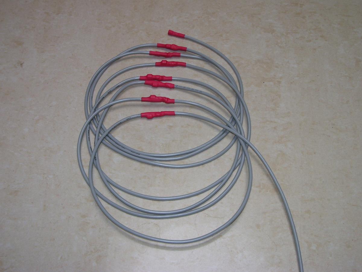
I make a "snake" sensor string:
temp-snake.jpg

Unfortunately, it's not always practical to measure temperatures using this.... for example, I measure 16 temperatures around two large hydronics tanks. They're 2.4m tall and over a metre diameter with inlets, outlets, heat exchangers and valves all over them. Using the star bus is the only practical way to do it.
 
Perhaps you should show the first three or four examples both with subroutines and without?

Here's a case of where 2 outputs should never be on at the same time. For 2 you could still get away with out the subs but 3 or more would require using a TST or more again.
I'm sure Ross has a better way of showing this..... (hint , hint....)

START
TSTLE T3
390
CALLSUB HEAT_LO
TSTLE T3
370
CALLSUB HEAT_HI
TSTGT T3 430

CALLSUB HEAT_OFF
END
HEAT_LO:
TSTLE T3 370
RET
SET OP1 1
SET OP2 0
RET
HEAT_HI

TSTGT T3 370
RET:
SET OP1 0
SET OP2 1
RET

HEAT_OFF
:
SET OP1 0
SET OP2 0

RET

NOW for it in Bitwise operands (I haven't tried either of these so I'm putting a disclaimer here)

START
TSTLE T3
370
ORB VAR1 1 VAR1
TSTLE T3 390
ORB VAR1 2 VAR1

TSTGT T3 430
ANDB VAR1 252 VAR1
ANDB VAR1 2 OP2
NOP
ANDB VAR1 1 OP1
Set OP2 0
END
I based this on using 8 bits (0-7 places) which is a sum of 255. The 252 for off is 255 -1 (bit 1) and -2 (bit 2). If you are using 16 bits etc. The highest sum of bits used (1+2+4+8+16+32+...) then subtract the bit you wish to set to 0 and this what you ANDB with to set the var or ram to a zero for the desired bit or bits.
"ANDB VAR1 1 OP1"
"NOP"
AND the 1st bit with 1 and set OP1 to the result of the AND operation. IE if the result is a 0 then OP1 is set to 0. If the result is true or a 1 then set OP1 to a 1.
If I'm wrong on this, then I hope Russ and CAI slap me and correct me.
 
Back
Top